一:前言
在鍵盤驅動代碼分析的筆記中,接觸到了input子系統.鍵盤驅動,鍵盤驅動將檢測到的所有按鍵都上報給了input子系統。Input子系統是所有I/O設備驅動的中間層,為上層提供了一個統一的界面。例如,在終端系統中,我們不需要去管有多少個鍵盤,多少個鼠標。它只要從input子系統中去取對應的事件(按鍵,鼠標移位等)就可以了。今天就對input子系統做一個詳盡的分析.
下面的代碼是基於linux kernel 2.6.25.分析的代碼主要位於kernel2.6.25/drivers/input下面.
二:使用input子系統的例子
在內核自帶的文檔Documentation/input/input-programming.txt中。有一個使用input子系統的例子,並附帶相應的說明。以此為例分析如下:
#include <linux/input.h>
#include <linux/module.h>
#include <linux/init.h>
#include <asm/irq.h>
#include <asm/io.h>
static void button_interrupt(int irq, void *dummy, struct pt_regs *fp)
{
input_report_key(&button_dev, BTN_1, inb(BUTTON_PORT) & 1);
input_sync(&button_dev);
}
static int __init button_init(void)
{
if (request_irq(BUTTON_IRQ, button_interrupt, 0, "button", NULL)) {
printk(KERN_ERR "button.c: Can't allocate irq %d\n", button_irq);
return -EBUSY;
}
button_dev.evbit[0] = BIT(EV_KEY);
button_dev.keybit[LONG(BTN_0)] = BIT(BTN_0);
input_register_device(&button_dev);
}
static void __exit button_exit(void)
{
input_unregister_device(&button_dev);
free_irq(BUTTON_IRQ, button_interrupt);
}
module_init(button_init);
module_exit(button_exit);
這個示例module代碼還是比較簡單,在初始化函數裡注冊了一個中斷處理例程。然後注冊了一個input device.在中斷處理程序裡,將接收到的按鍵上報給input子系統。
文檔的作者在之後的分析裡又對這個module作了優化。主要是在注冊中斷處理的時序上。在修改過後的代碼裡,為inputdevice定義了open函數,在open的時候再去注冊中斷處理例程。具體的信息請自行參考這篇文檔。在資料缺乏的情況下,kernel自帶的文檔就是剖析kernel相關知識的最好資料.
文檔的作者還分析了幾個api函數。列舉如下:
1):set_bit(EV_KEY, button_dev.evbit);
set_bit(BTN_0, button_dev.keybit);
分別用來設置設備所產生的事件以及上報的按鍵值。Struct iput_dev中有兩個成員,一個是evbit.一個是keybit.分別用表示設備所支持的動作和按鍵類型。
2): input_register_device(&button_dev);
用來注冊一個input device.
3): input_report_key()
用於給上層上報一個按鍵動作
4): input_sync()
用來告訴上層,本次的事件已經完成了.
5): NBITS(x) - returns the length of a bitfield array in longs for x bits
LONG(x) - returns the index in the array in longs for bit x
BIT(x) - returns the index in a long for bit x
這幾個宏在input子系統中經常用到。上面的英文解釋已經很清楚了。
三:input設備注冊分析.
Input設備注冊的接口為:input_register_device()。代碼如下:
int input_register_device(struct input_dev *dev)
{
static atomic_t input_no = ATOMIC_INIT(0);
struct input_handler *handler;
const char *path;
int error;
__set_bit(EV_SYN, dev->evbit);
/*
* If delay and period are pre-set by the driver, then autorepeating
* is handled by the driver itself and we don't do it in input.c.
*/
init_timer(&dev->timer);
if (!dev->rep[REP_DELAY] && !dev->rep[REP_PERIOD]) {
dev->timer.data = (long) dev;
dev->timer.function = input_repeat_key;
dev->rep[REP_DELAY] = 250;
dev->rep[REP_PERIOD] = 33;
}
在前面的分析中曾分析過。Input_device的evbit表示該設備所支持的事件。在這裡將其EV_SYN置位,即所有設備都支持這個事件.如果dev->rep[REP_DELAY]和dev->rep[REP_PERIOD]沒有設值,則將其賦默認值。這主要是處理重復按鍵的.
if (!dev->getkeycode)
dev->getkeycode = input_default_getkeycode;
if (!dev->setkeycode)
dev->setkeycode = input_default_setkeycode;
snprintf(dev->dev.bus_id, sizeof(dev->dev.bus_id),
"input%ld", (unsigned long) atomic_inc_return(&input_no) - 1);
error = device_add(&dev->dev);
if (error)
return error;
path = kobject_get_path(&dev->dev.kobj, GFP_KERNEL);
printk(KERN_INFO "input: %s as %s\n",
dev->name ? dev->name : "Unspecified device", path ? path : "N/A");
kfree(path);
error = mutex_lock_interruptible(&input_mutex);
if (error) {
device_del(&dev->dev);
return error;
}
如果inputdevice沒有定義getkeycode和setkeycode.則將其賦默認值。還記得在鍵盤驅動中的分析嗎?這兩個操作函數就可以用來取鍵的掃描碼和設置鍵的掃描碼。然後調用device_add()將input_dev中封裝的device注冊到sysfs
list_add_tail(&dev->node, &input_dev_list);
list_for_each_entry(handler, &input_handler_list, node)
input_attach_handler(dev, handler);
input_wakeup_procfs_readers();
mutex_unlock(&input_mutex);
return 0;
}
這裡就是重點了。將inputdevice 掛到input_dev_list鏈表上.然後,對每一個掛在input_handler_list的handler調用input_attach_handler().在這裡的情況有好比設備模型中的device和driver的匹配。所有的inputdevice都掛在input_dev_list鏈上。所有的handle都掛在input_handler_list上。
看一下這個匹配的詳細過程。匹配是在input_attach_handler()中完成的。代碼如下:
static int input_attach_handler(struct input_dev *dev, struct input_handler *handler)
{
const struct input_device_id *id;
int error;
if (handler->blacklist && input_match_device(handler->blacklist, dev))
return -ENODEV;
id = input_match_device(handler->id_table, dev);
if (!id)
return -ENODEV;
error = handler->connect(handler, dev, id);
if (error && error != -ENODEV)
printk(KERN_ERR
"input: failed to attach handler %s to device %s, "
"error: %d\n",
handler->name, kobject_name(&dev->dev.kobj), error);
return error;
}
如果handle的blacklist被賦值。要先匹配blacklist中的數據跟dev->id的數據是否匹配。匹配成功過後再來匹配handle->id和dev->id中的數據。如果匹配成功,則調用handler->connect().
來看一下具體的數據匹配過程,這是在input_match_device()中完成的。代碼如下:
static const struct input_device_id *input_match_device(const struct input_device_id *id,
struct input_dev *dev)
{
int i;
for (; id->flags || id->driver_info; id++) {
if (id->flags & INPUT_DEVICE_ID_MATCH_BUS)
if (id->bustype != dev->id.bustype)
continue;
if (id->flags & INPUT_DEVICE_ID_MATCH_VENDOR)
if (id->vendor != dev->id.vendor)
continue;
if (id->flags & INPUT_DEVICE_ID_MATCH_PRODUCT)
if (id->product != dev->id.product)
continue;
if (id->flags & INPUT_DEVICE_ID_MATCH_VERSION)
if (id->version != dev->id.version)
continue;
MATCH_BIT(evbit, EV_MAX);
MATCH_BIT(,, KEY_MAX);
MATCH_BIT(relbit, REL_MAX);
MATCH_BIT(absbit, ABS_MAX);
MATCH_BIT(mscbit, MSC_MAX);
MATCH_BIT(ledbit, LED_MAX);
MATCH_BIT(sndbit, SND_MAX);
MATCH_BIT(ffbit, FF_MAX);
MATCH_BIT(swbit, SW_MAX);
return id;
}
return NULL;
}
MATCH_BIT宏的定義如下:
#define MATCH_BIT(bit, max) \
for (i = 0; i < BITS_TO_LONGS(max); i++) \
if ((id->bit & dev->bit) != id->bit) \
break; \
if (i != BITS_TO_LONGS(max)) \
continue;
由此看到。在id->flags中定義了要匹配的項。定義INPUT_DEVICE_ID_MATCH_BUS。則是要比較inputdevice和inputhandler的總線類型。INPUT_DEVICE_ID_MATCH_VENDOR,INPUT_DEVICE_ID_MATCH_PRODUCT,INPUT_DEVICE_ID_MATCH_VERSION分別要求設備廠商。設備號和設備版本.
如果id->flags定義的類型匹配成功。或者是id->flags沒有定義,就會進入到MATCH_BIT的匹配項了.從MATCH_BIT宏的定義可以看出。只有當iput device和input handler的id成員在evbit, keybit,…swbit項相同才會匹配成功。而且匹配的順序是從evbit, keybit到swbit.只要有一項不同,就會循環到id中的下一項進行比較.
簡而言之,注冊input device的過程就是為input device設置默認值,並將其掛以input_dev_list.與掛載在input_handler_list中的handler相匹配。如果匹配成功,就會調用handler的connect函數.
四:handler注冊分析
Handler注冊的接口如下所示:
int input_register_handler(struct input_handler *handler)
{
struct input_dev *dev;
int retval;
retval = mutex_lock_interruptible(&input_mutex);
if (retval)
return retval;
INIT_LIST_HEAD(&handler->h_list);
if (handler->fops != NULL) {
if (input_table[handler->minor >> 5]) {
retval = -EBUSY;
goto out;
}
input_table[handler->minor >> 5] = handler;
}
list_add_tail(&handler->node, &input_handler_list);
list_for_each_entry(dev, &input_dev_list, node)
input_attach_handler(dev, handler);
input_wakeup_procfs_readers();
out:
mutex_unlock(&input_mutex);
return retval;
}
handler->minor表示對應input設備節點的次設備號.以handler->minor右移五位做為索引值插入到input_table[ ]中..之後再來分析input_talbe[ ]的作用.
然後將handler掛到input_handler_list中.然後將其與掛在input_dev_list中的input device匹配.這個過程和input device的注冊有相似的地方.都是注冊到各自的鏈表,.然後與另外一條鏈表的對象相匹配.
五:handle的注冊
int input_register_handle(struct input_handle *handle)
{
struct input_handler *handler = handle->handler;
struct input_dev *dev = handle->dev;
int error;
/*
* We take dev->mutex here to prevent race with
* input_release_device().
*/
error = mutex_lock_interruptible(&dev->mutex);
if (error)
return error;
list_add_tail_rcu(&handle->d_node, &dev->h_list);
mutex_unlock(&dev->mutex);
synchronize_rcu();
/*
* Since we are supposed to be called from ->connect()
* which is mutually exclusive with ->disconnect()
* we can't be racing with input_unregister_handle()
* and so separate lock is not needed here.
*/
list_add_tail(&handle->h_node, &handler->h_list);
if (handler->start)
handler->start(handle);
return 0;
}
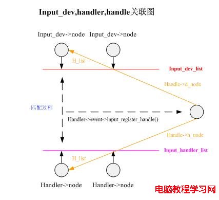
在這個函數裡所做的處理其實很簡單.將handle掛到所對應input device的h_list鏈表上.還將handle掛到對應的handler的hlist鏈表上.如果handler定義了start函數,將調用之.
到這裡,我們已經看到了input device, handler和handle是怎麼關聯起來的了.以圖的方式總結如下: